Welcome, Guest
Username: Password: Remember me
  • Page:
  • 1

TOPIC: IO configs on Arduino MEGA 2560

IO configs on Arduino MEGA 2560 5 years 3 months ago #10131

  • Maverick
  • Maverick's Avatar
  • OFFLINE
  • Senior Boarder
  • Posts: 64
  • Karma: 0
Hi everyone,
I have an Arduino MEGA 2560 that I intend to use with Proview. I have a small 3 to 6V DC pump, a HC-SR04 ultrasonic sensor module and a few LEDs to use for a small project.

1-I'm planning to try with USB first. I have followed Marc's tutorial but as a beginner, I'm still confused about the script in the Arduino sketch: I still couldn't figure out how are the Arduino pins (analog inputs, analog outputs, digital inputs, digital outputs... and their number) and the channels in Proview could be related... and more importantly how to set it up to work with the Arduino MEGA 2560

2-After testing with USB, I intend to use it with Modbus TCP/IP. For now, I'm still having trouble connecting my Arduino Ethernet Shield to my PC (can't connect it directly with my PC)... And once again, I need to understand how the Arduino pins (analog inputs, analog outputs, digital inputs, digital outputs... and their number) and the channels in Proview could be related by using Modbus TCP/IP. I have followed Ben's tutorial with the Schneider Electric Momentum PLC, but it still left me wondering how to proceed with an Arduino...

My configs are Proview V5.5 on Ubuntu MATE 16.04 amd64

Looking forward for your help, guys

/Maverick
Last Edit: 5 years 3 months ago by Maverick.
The administrator has disabled public write access.

IO configs on Arduino MEGA 2560 5 years 3 months ago #10135

  • claes
  • claes's Avatar
  • OFFLINE
  • Platinum Boarder
  • Posts: 3176
  • Thank you received: 501
  • Karma: 133
Hi Maverick,

1. You can read about how to configure the Arduino I/O in Guide to IO Systems. The pin number should be specified in the Number attribute of the channel object.

2. I haven't used Mudbus so I don't know all the details, but again you can read about Modbus TCP in Guide to IO System. You specify a function code and an address, and for registers (Ai and Ao) it's the address and channel order that determines which pin a channel will correspond to. For coils (Do) and discrete inputs (Di) also the Number attribute is involved and specifies a bit number. It's a bit complicated so you have to read the guide. You also have to figure out which function codes are supported by Mudbus and which addresses to use.

/Claes
The administrator has disabled public write access.

IO configs on Arduino MEGA 2560 5 years 3 months ago #10136

  • Maverick
  • Maverick's Avatar
  • OFFLINE
  • Senior Boarder
  • Posts: 64
  • Karma: 0
ok Claes,
Thanks for your reply, I'll read all about them and I'll scratch my head a bit...
Until then, about the "Arduino sketch", I uploaded it into my Arduino MEGA 2560, the TX and RX leds just blinked a bit... since it's labeled with "arduino_uno" I wonder what lines of codes I should edit as a workaround to make it compatible with my MEGA 2560...

/Maverick
The administrator has disabled public write access.

IO configs on Arduino MEGA 2560 5 years 3 months ago #10137

  • marc
  • marc's Avatar
  • OFFLINE
  • Platinum Boarder
  • Posts: 710
  • Thank you received: 70
  • Karma: 24
Hi Maverick,

What I can remember concerning the MEGA 2560 it is compatible with the "arduino_uno" sketch.
Be sure the baudrate are the same in the sketch and the configuration of Proview.
Blinking "a bit" is not enough and it can be the stty-settings.
Search the forum on stty .....

A couple of years ago I gave an Uno/Ethershield and Mudbus a try.
What I can remember this combination was working but not stable.

/Marc
Please, use the Wiki if you succeeded your project or solved your problem. Share your work, so we can learn from each other.
The administrator has disabled public write access.

IO configs on Arduino MEGA 2560 5 years 2 months ago #10177

  • Maverick
  • Maverick's Avatar
  • OFFLINE
  • Senior Boarder
  • Posts: 64
  • Karma: 0
Hi everyone,
First, I'd like to thank Ben for his tutorial on modbus TCP/IP with logic IO, I've successfully replicated it on my Arduino MEGA 2560 + W5100 Ethernet Shield R3 with the Mudbus library from Martin.

Now, I'm working with an HC-SR04 ultrasonic sensor.
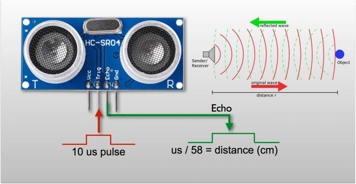
For those who are not familiar with this device, let me explain it with more details:
It sends and receives ultrasonic waves to measure distance (just like bats)
It has four pins:
-VCC and GND: for powering the device (the 5V from any Arduino is enough)
-Trig: connected to a digital pin on the Arduino, when it receives a digital output signal from the Arduino, the transmitter sends an ultrasonic pulse.
-Echo: connected to a digital pin on the Arduino, when the ultrasonic pulse bounced back from an object and made it into the receiver, the signal becomes a digital input to the Arduino, and the measured distance could be set up to be shown on the Arduino IDE serial monitor.


For further details, there's some code to do it with Arduino IDE:

/*
* created by Rui Santos, randomnerdtutorials.com
*
* Complete Guide for Ultrasonic Sensor HC-SR04
*
Ultrasonic sensor Pins:
VCC: +5VDC
Trig : Trigger (INPUT) - Pin11
Echo: Echo (OUTPUT) - Pin 12
GND: GND
*/
int trigPin = 11;
int echoPin = 12;
long duration, cm, inches;
void setup() {
//Serial Port begin
Serial.begin (9600);
//Define inputs and outputs
pinMode(trigPin, OUTPUT);
pinMode(echoPin, INPUT);
}
void loop()
{
// The sensor is triggered by a HIGH pulse of 10 or more microseconds.
// Give a short LOW pulse beforehand to ensure a clean HIGH pulse:
digitalWrite(trigPin, LOW);
delayMicroseconds(5);
digitalWrite(trigPin, HIGH);
delayMicroseconds(10);
digitalWrite(trigPin, LOW);
// Read the signal from the sensor: a HIGH pulse whose
// duration is the time (in microseconds) from the sending
// of the ping to the reception of its echo off of an object.
pinMode(echoPin, INPUT);
duration = pulseIn(echoPin, HIGH);
// convert the time into a distance
cm = (duration/2) / 29.1;
inches = (duration/2) / 74;
Serial.print(inches);
Serial.print("in, ");
Serial.print(cm);
Serial.print("cm");
Serial.println();
delay(250);
}


And an alternative code with a library called "NewPing":

/*
* Posted on randomnerdtutorials.com
* created by playground.arduino.cc/Code/NewPing
*/
#include <NewPing.h>
#define TRIGGER_PIN 12
#define ECHO_PIN 11
#define MAX_DISTANCE 200
NewPing sonar(TRIGGER_PIN, ECHO_PIN, MAX_DISTANCE); // NewPing setup of pins and
maximum distance.
void setup() {
Serial.begin(9600);
}
void loop() {
delay(50);
unsigned int uS = sonar.ping_cm();
Serial.print(uS);
Serial.println(‘‘cm’’);
}


Now, the problem I'm facing:

1-The Echo pin has to be configured as a digital input and has to be connected to a digital pin on the Arduino, and by using the "pulseIn" function in the Arduino IDE, the resulting measured distances are integer values.
2-I want to display such distances in the form of a bar or a trend on Ge on Proview (which require analog values). If I'm not mistaken, digital-type channels are compatible with digital values (0 or 1). If I use analog-type channels, I'm afraid it would not be able to read values (the Echo pin of the ultrasonic sensor has to be connected to a digital pin on the Arduino), and I'm not sure if integer-type channels could solve it.


And finally, my questions:

1-Which type of channel should I use on my modbus module on Proview?
2-I'd like to know more about how to use integer-type channels. With which type of physical IO interface could they be used: analog or digital, or maybe both?


Any help appreciated
Best regards


/Maverick
Attachments:
The administrator has disabled public write access.
  • Page:
  • 1
Time to create page: 8.496 seconds