Welcome, Guest
Username: Password: Remember me
  • Page:
  • 1
  • 2

TOPIC: Arduino Modbus TCP module and channels

Arduino Modbus TCP module and channels 5 years 1 month ago #10230

  • Maverick
  • Maverick's Avatar
  • OFFLINE
  • Senior Boarder
  • Posts: 64
  • Karma: 0
Hi everyone,
I'm working on a project involving the Arduino MEGA 2560 and Modbus TCP. (I am using the "mudbus" library)
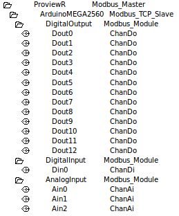
I've set a Modbus master object, a Modbus slave object, 13 Do channels, one Di channel and 3 Ai channels.
I made one Modbus object for each type of channel (function code Write multiple coils for the one with Do channels, Read coils for the one with Di channel and Read holding registers with Ai channels).
I represented the Do and Di channels in bit8, and the Ai in Int16.

I've set the number of channels in the following manner:
Do channels - from 0 to 12
Di channel - 13
Ai channels - 14 to 16

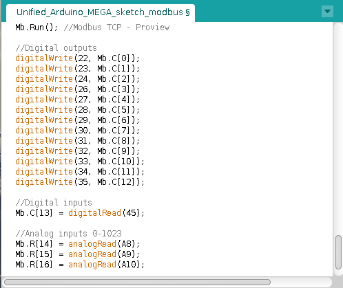
And I've set the Modbus settings in the Arduino IDE sketch exactly in the same pattern - according to the channel numbers

I performed a number of tests so far on the Do Channels, and I notice such anomalies:
Only channels from number 0 to 7 could be turned on and off (by setting their value in the object graph in the runtime) and their corresponding devices respond correctly. But, even though the channels number 8 to 12 could be turned on and off as well on Proview, there's no response from their corresponding devices. I've tried bit16 representation but it's still not working, and worse, the channels' relationship with their corresponding devices got distorted a bit (When turning on the value of a channel, it's the corresponding device of an another channel which respond by turning on)

So, please, I need help about to find out the answers to the following questions:
-Is it correct to configure the Modbus input/output settings in the Arduino IDE according to the channel numbers on Proview?
-Is there something to have with the address setting in the Modbus module?
-When and how to use the different representations: bit8, bit16, bit32, bit64...? And how could it affect the Modbus settings on the Arduino IDE sketch?
-Could I place channels of different types into the same Modbus module? If yes, how should I proceed?

I've sent screenshots of my settings on Arduino IDE and on Proview

Any help greatly appreciated.
Best regards.

/Maverick
Attachments:
Last Edit: 5 years 1 month ago by Maverick.
The administrator has disabled public write access.

Arduino Modbus TCP module and channels 5 years 4 weeks ago #10232

  • claes
  • claes's Avatar
  • OFFLINE
  • Platinum Boarder
  • Posts: 3177
  • Thank you received: 502
  • Karma: 133
Hi Maveric,

You should use representation Bit8 and number the first 8 Di channels 0-7 and the next 8 also 0-7 etc.

There is a difference between Bit 8 and Bit16 because the network format for Modbus TCP is Big endian while both x86 and arduino are Little endian. Thus a 16-bit word is byte swapped while two 8 bit are not. Coils and discrete inputs should not be byte swapped while registers that are 16 bit words should.

You can mix differnt channel types but you have to make sure that the received message is interpreted in in the correct way regarding the size and swapping of each channel.

/Claes
The administrator has disabled public write access.

Arduino Modbus TCP module and channels 5 years 4 weeks ago #10233

  • Maverick
  • Maverick's Avatar
  • OFFLINE
  • Senior Boarder
  • Posts: 64
  • Karma: 0
Hi Claes,
Thank you very much for your answer. Just to make sure: if I set the numbers 0-7, 0-7 ... in bit8 representation, wouldn't there a bit of confusion between channels with the same number? And why?

/Maverick
The administrator has disabled public write access.

Arduino Modbus TCP module and channels 5 years 4 weeks ago #10234

  • claes
  • claes's Avatar
  • OFFLINE
  • Platinum Boarder
  • Posts: 3177
  • Thank you received: 502
  • Karma: 133
The channels are describing the content of the message area with their order. So the first 0-7 will point to the first byte, and the second 0-7 do the second byte etc. Actually it's the di channel with number 0 that 'allocates' a new byte in the message, and the next channels will be positioned in this byte until another channel with number 0 allocates another byte.

/Claes
The administrator has disabled public write access.

Arduino Modbus TCP module and channels 5 years 4 weeks ago #10235

  • Maverick
  • Maverick's Avatar
  • OFFLINE
  • Senior Boarder
  • Posts: 64
  • Karma: 0
Thanks a lot, Claes

/Maverick
The administrator has disabled public write access.

Arduino Modbus TCP module and channels 5 years 4 weeks ago #10249

  • Maverick
  • Maverick's Avatar
  • OFFLINE
  • Senior Boarder
  • Posts: 64
  • Karma: 0
hi Claes,
Thanks for your help about the Do channels above. But still, there's something that I don't understand about channels... to be more precise, about the channel numbering when working with different types of channels with different representations, for example, I have a Do (bit8) with some N channel number, and I have to set the number of the next channel, which is an Ai (Int16) type, do I have to get back to 0 or setting this number to N+1 ?
Also, taking into account your explanation about Little/Big Endian, and byte swapping, I'm still a bit confused...
I'm working on three modbus modules, the first contains 13 Do channels, the second contains 1 Di channels, and the third 3 Ai channels.
As you advised, on the first modbus module, I've set the number of channels to 0-7,0-4. working fine, but then what about the channel numbering on the Di and especially the Ai channels? do I have to start to 0 when switching to another type of channel? or do I have to continue? or should I place the Ai channels first in the numbering order?

/Maverick
The administrator has disabled public write access.
  • Page:
  • 1
  • 2
Time to create page: 8.940 seconds