Welcome, Guest
Username: Password: Remember me
  • Page:
  • 1
  • 2

TOPIC: The caLC system and the HYDRA Controller Family

The caLC system and the HYDRA Controller Family 6 years 1 month ago #9588

  • TheGiants
  • TheGiants's Avatar
  • OFFLINE
  • Fresh Boarder
  • Posts: 12
  • Karma: 0
Hi,

first of all, I would like to say thanks to the development team for their Proview, support and inspiration!

Parallel with this post, we present some specific applications in the Project Forum that helped to create the first industrial controller which directly supports the Proview.

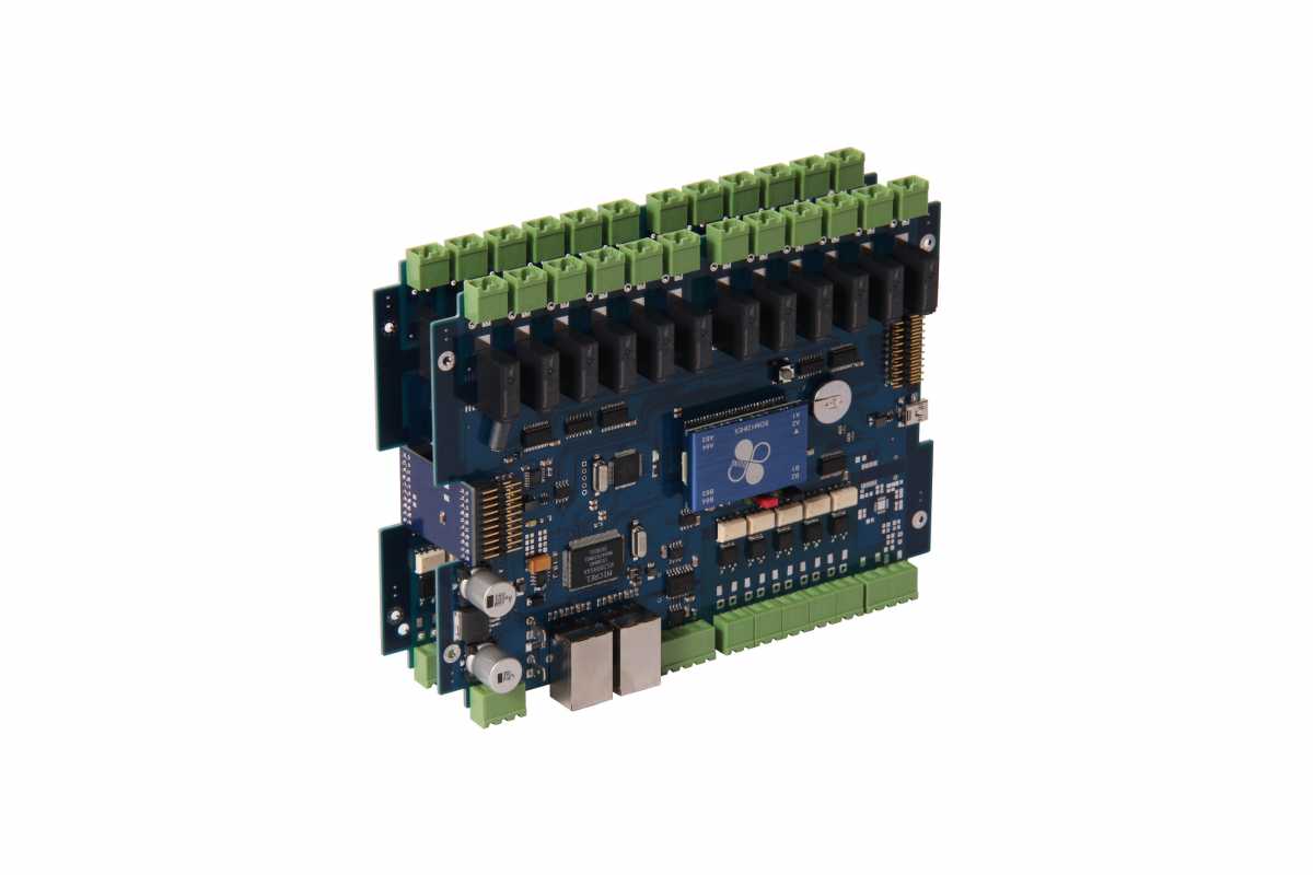
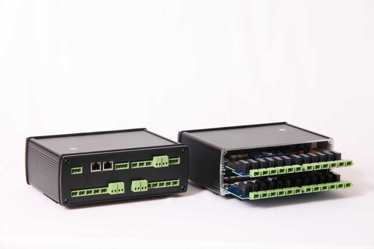
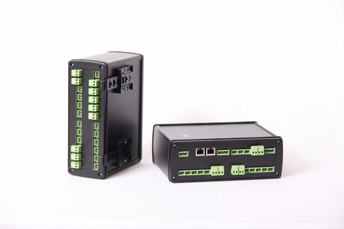
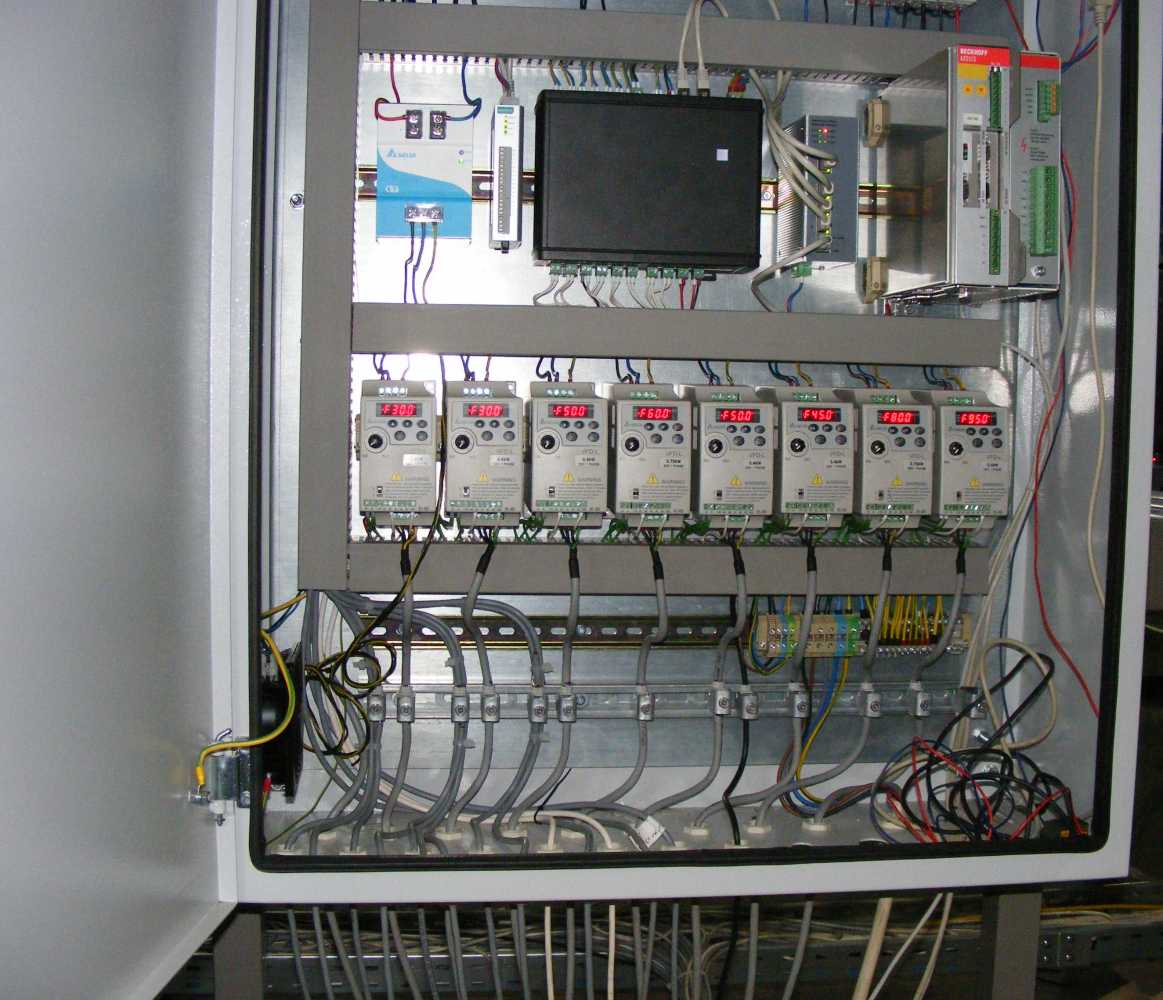
The development of our caLC controller family has been completed and ready for production!

hydra_1.jpg

hydra_2.jpg

hydra_3.jpg

hydra_4.jpg


Our caLC (Computerized Adaptive Logical Controller) system is based on the
concept of combining the traditional and robust PLC hardware with the flexibility
and the wide range of application possibilities of the computers. We realized our
goals by designing a highly reliable I/O system which is built around an industrial
computer. The result of our development is a compact and scalable system,
which is adjustable according to the needs of the application.

If you have any questions regarding the details our controller feel free to ask. 

Regards

Miklós
Last Edit: 6 years 1 month ago by TheGiants.
The administrator has disabled public write access.

The caLC system and the HYDRA Controller Family 6 years 1 month ago #9591

Our (Lindsay) sister company (Elecsys) has a very good gateway product, RediGate, that is a mature gateway product with Linux at its core. Separating the gateway and logic processor components is a safe approach to me. I think your product might just fill the gap and I wonder how sustainable this combination would be over a long period of time.

Is there any technical documentation available on one caCL system please?
The administrator has disabled public write access.

The caLC system and the HYDRA Controller Family 6 years 1 month ago #9592

  • TheGiants
  • TheGiants's Avatar
  • OFFLINE
  • Fresh Boarder
  • Posts: 12
  • Karma: 0
Hi,

I upload information continuously.

M
The administrator has disabled public write access.

The caLC system and the HYDRA Controller Family 6 years 1 month ago #9595

  • TheGiants
  • TheGiants's Avatar
  • OFFLINE
  • Fresh Boarder
  • Posts: 12
  • Karma: 0
Hi,

to understand the structure of the caLC system the following definitions are
necessary.

MODULE: The module is the name of the components which have their own
functionality. The caLC system is built up of these modules. It includes the
controller and the I/O modules. The modules are connected to each other via the
backplane bus.

BACKPLANE BUS: The backplane bus is a PCB which connects the modules to
each other. Besides the wiring of the BUS, this PCB also contains the address
translators which are necessary to be able to use the same modules within one
UNIT.

UNIT: The units are the sum of the modules, placed in one housing. The housing
is also the part of a UNIT.

SUBMODULE: The sub modules are expendable components, which are
connected directly to the modules, not through the backplanes. Submodules are
contained exclusively by the I/O modules.

Modules, structure

Smart Module Zero - SMZ

The SMZ is based on the Vortex86EX SoC chip (SOM128EX). A special Linux
distribution is running on the x86 architecture processor (Of course it is possible
to run other type of operation systems.). The operation system manages the
common resources; the control of the I/O is done by the caLC Core software
module. Two watchdog circuits support the fault-tolerant operation of the OS. The
SMZ module is connected to the Backplane Bus through the bus arbiter. Ethernet,
RS485 and USB interfaces also can be found on this module. The Ethernet switch
provides opportunity to create a daisy chain topology. In addition to the above,
the module also contains digital input and output channels. The digital I/O ports
are isolated and potential independent.

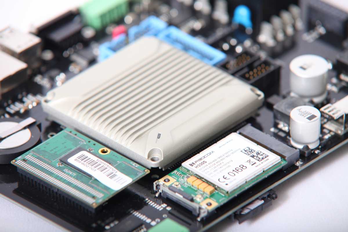
Smart Module One – SMO

The SMO is based on the Vortex86MX SoC chip (SOM304RD). A special Linux
distribution is running on the x86 architecture processor (Of course it is possible
to run other type of operation systems.). The operation system manages the
common resources; the control of the I/O is done by the caLC Core software
module. Two watchdog circuits support the fault-tolerant operation of the OS. The
SMO module is connected to the Backplane Bus through the bus arbiter. Ethernet,
RS485, 1-Wire, RS232, USB, 3G and 4G interfaces also can be found on this
module. The Ethernet switch provides opportunity to create a daisy chain
topology. In addition to the internal 2 GB data storage of the SOM304 it is
possible to connect an ATA DOM data storage which can be maximum 128GB.
This modul has not got any I/O ports.

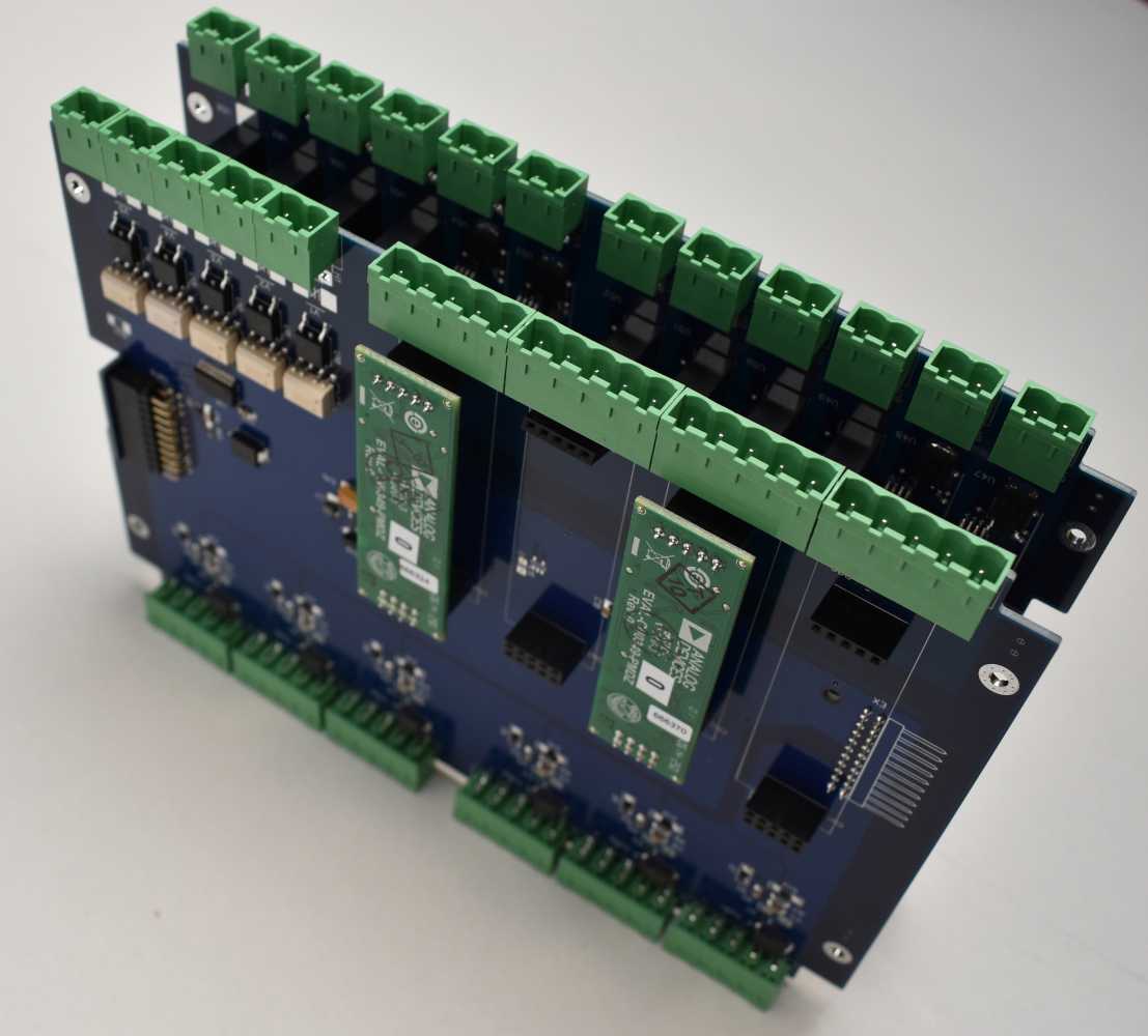
Digital Input Output Module – DIOM

The digital I/O module is connected to the Backplane Bus, which provides the
address transformation of the module and does the active bus selection. Through
this bus the I/O is controlled by the SMZ and/or the SMO modules. The I/O ports
are isolated and potential independent.

Analog Input Output Module – AIOM

The Analog I/O module is connected to the Backplane Bus, which provides the
address transformation of the module and does the active bus selection. Through
this bus the I/O is controlled by the SMZ and/or the SMO modules. The module
contains fix analog input channels (ADC) as well as place for optional
submodules. Many type of submodules can be used, currently there are ones
which are capable for conductivity measurement, temperature measurement and
producing analog output signal (DAC).

Structure of a UNIT

The UNIT is placed in a robust cast-pulled aluminium housing. Up to 3 modules
can be in one UNIT. The possible variations of the modules in a UNIT are the
following:

a. SMZ
b. SMO
c. SMZ + DIOM
d. SMZ + AIOM
e. SMZ + DIOM + DIOM
f. SMZ + DIOM + AIOM
g. SMZ + AIOM + AIOM
h. SMO + DIOM + DIOM
i. SMO + DIOM + AIOM
j. SMO + AIOM + AIOM
k. SMO + SMZ
l. SMO + SMZ + DIOM
m. SMO + SMZ + AIOM

Fault-tolerant, redundant operation

The SMZ and the SMO module also have a failsafe controller, that allows
controlling the various error states. It is possible to send messages to an external
supervisor via Ethernet or RS485 channels, in case of the malfunctioning or
inoperable state of the SoC. It is possible to restart the SoC with external
commands.
The digital channel controllers have POR (Power On Reset) logic. This allows to
predetermine Low or High levels of the default switch-on status on each channel
when they are powered on. In addition, the digital channel controllers also have
an independent WDT (Watchdog Timer). In case of losing the I/O control, the
outputs are set to the pre-programmed failsafe status.

The structure of the UNITS makes possible to make a redundant architecture. The
operation of a UNIT can also be redundant, if it has an SMZ and an SMO
controller. In this case the duplicated internal bus offers the possibility of
transferring the control between the primary and the backup controller. The SMO
is the primary and the SMZ is the secondary controller. The connection of the
UNITS can be solved through duplicated or simple communication channels, as
the internal backplane bus is transparent. In case of the failure of any SM(Smart
Module), the other active SM also has access to the other module’s peripheral
adapters, so it can also control the communication and I/O channels. For
example, if the SMO fails then the SMZ can take control of the SMO’s 4G channel
and may maintain the GSM connection.
Attachments:
Last Edit: 6 years 1 month ago by TheGiants.
The administrator has disabled public write access.
The following user(s) said Thank You: Jansen van Vuuren

The caLC system and the HYDRA Controller Family 6 years 1 month ago #9596

  • pongraczi
  • pongraczi's Avatar
  • OFFLINE
  • Senior Boarder
  • Posts: 58
  • Thank you received: 4
  • Karma: 0
Hi Jansen,

I just check your Redigate product, seems very good gateway, as you mentioned.
I will spend more time on that site to look around deeply.
Thanks for the link!

István
The administrator has disabled public write access.
The following user(s) said Thank You: Jansen van Vuuren

The caLC system and the HYDRA Controller Family 6 years 1 month ago #9599

  • TheGiants
  • TheGiants's Avatar
  • OFFLINE
  • Fresh Boarder
  • Posts: 12
  • Karma: 0
Hi,

currently we are designing 6-8 different modules. Right now we have five different modules available/ready to test.

These are the following:

1st C-caLC SMZ - Smart Module Zero (tested, ready for production)
2nd C-caLC SMO – Smart Module One (v2.x test unit, preparing for production)
3rd C-caLC DIOM – Digital I/O Module (tested, ready for production)
4th C-caLC AIOM – Analog I/O Module (under testing)
5th C-caLC SAIOM – Simplified Analog I/O Module (tested, ready for production)

I would also mention the C-caLC SMCM – Stepper/Servo Motor Control Module which is in design planning phase. This will be able to serve four engines (P<200W).

I have attached additional documents.

Regards

M
Attachments:
The administrator has disabled public write access.
The following user(s) said Thank You: Jansen van Vuuren
  • Page:
  • 1
  • 2
Time to create page: 8.325 seconds